Electronic Speedometer how to and why from NVU
NVU Tech Team on 3rd Feb 2016

Electronic speedometers are also sometimes referred to as programmable speedometers, the terms are not interchangable however. Electronic speedometers have been in use by car, vehicle, boat, military and just about anything that moves for about 40 years now.
What is an electronic speedometer and why would I need one?
Electronic speedometers accept an input from some sort of signal source- more on this subject in a bit. This signal source is generally a speed sender (sometimes called a pulse generator or electonic speedometer pickup) located in the transmission, the vehicle's PCM (power train control module , ECM, computer) or a GPS sender (which can be mounted in the vehicle or the gauge itself). Old style mechanical speedometers used a cable directly connected to the tailshaft on the transmission, transfer case or even a wheel hub. While these are still in use today in the aftermarket, the trend has been going electonic for quite some time. The benefit of electonic speedometers is they can be custom tailored to the individual vehicle by setting DIP-switches, programming via the LCD or hard programmed at the factory.
The reason for the increase in use for the aftermarket community is due to several factors:
1. Many if not most of the components for building today's enthusiast built vehicles are newer, many donor vehicles are form the 80s and 90s when the OEs started using electronic speed senders to monitor vehicle speed for cruise control, emissions, etc.
2. With the wide range of vehicle types being built today (pro-touring, tuner, race, off-road/Jeep) the need for a speedometer with a wider range of operation was required. Also this wide variety of vehicles being built by today's builders leads to a wider range of maximum speeds. A vehicle that spends some time on the track may want a maximum speedo of 140, 160 or even 200 MPH, while a lifted truck or rock crawler will want more resolution whith a maximum of 80, 100 120 or 140MPH.
3. The international market has really opened up and calibration of the speedometer is critical in proper speeed reading of metric (km/h, KPH) speeds. Here at NVU we can load a metric speedometer program creating a suitable product for use overseas without needing to change magnetic wheels or odometer gears on a mechanical unit.
What is the difference between an electonic speedometer and a programmable speedometer?
An electrical speedometer reads pulses (signal) from the signal source. This is read by a processor which drives the pointer (not a needle) and odometer to do the right things. The electronic speedometer is either permanantly programmed to read a specific number of pulses per mile (or kilometer) and read a certain speed; or it may have an external switch, or DIP-switches, that can be altered to change the vehicle speed reading on the dial. While this works well if you know the exact number of pluses coming from the sender, some trial and error may be required. The difficulty in this is with so many types of senders being spun by different sized tires, rear end gears, final drive, etc, it is nearly impossible sometimes to know where to start. Electronic speedmeters read pulses per mile (PPM) and the range can vary from 3000-200,000 per mile, quite a gap to fill.
A programmable electronic speedometer operates in a similar way but has the added feature of user-directed programming. All NVU electronic speedometers are fully programmable. The speedometer can be programmed to the proper sender input by driving a mile or by entering the pulse count manually. The drive-a mile technique is the preferred method as this will give the most accurate result provided the mile is indeed a mile. This method will also be completed in the time it takes to drive a mile, about a minute or two! Other features can be programmed into NVU electronic programmable speedometers; service intervals, speed warnings, integrated tripmeters can all be set by the push of a button. If any electronic speedometer adjustment is required, the drive a mile function can be re-calibrated again or at any time there is a change to the vehicle like gears or tire size. Its just that easy. All NVU electronic speedometers used in aftermarket kits have these features.
Below are some videos on how some of the NVU programmable speedometers are calibrated, or how to do electronic speedometer calibration:
What is a GPS Speedometer?
A GPS speedometer is basically an electronic speedometer with a GPS sender inside the gauge. Any NVU programmable speedometer can be a GPS speedometer by using a GPS speed sender. While NVU does manufacture GPS speedometers for open vehicles such as boats or motorcycles. We have also found that mounting the speedometer in some vehicles will not yield good results due to metal dash, roof, cages, etc. This is due to the sender needing to be able to see at least 3 Global position satellites at all times. The integrated sender works fine but with the wide range of builds being done today, the arrangement of metals around the vehicle is not predictable and therefore NVU does not produce a speedometer with integrated GPS for that reason alone. To have a better result, NVU reccomends using a GPS SPEED SENDER. This can remotely mount ANYWHERE and then have a clear signal. The downside to GPS senders is a brief lag at startup and if you are in a tunnel, well you are on your own. The only reason to use a GPS speedometer or sender is if there is absolutely no other way to pick up a speed signal. Viper transmissions do not have a speed sender in them, but other than that, 99.9% of transmissions have some sort of sender or the PCM will output a signal.
Analog speedometer vs Digital
An electronic analog speedometer uses a pointer and gauge dial to display vehicle speed where a digital uses digits displayed on a screen. Digital speedometers are always electronic but analog and be electronic or mechanical. Digital refers to the display, not the ability to read electronically. At NVU we only use analog style as we strive to provide the most stunning, easy to read designs available in a classic style; something that just can't be accomplished with the digital. The odometers are always digital, they may be a roller wheel or LCD but they are always digital.
Electronic speedometer wiring diagram
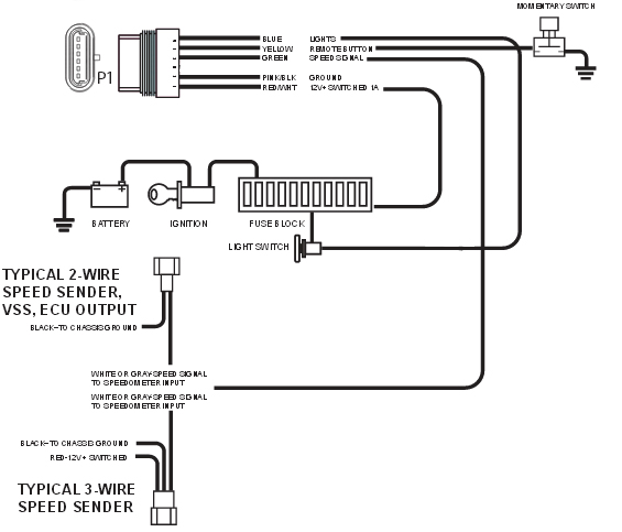
This sounds complicated but its really quite easy. All gauges require 4 things to be connected: Power, Ground, Lights and signal. That really is it. There may be additional wiring for other features like programming button, warning outputs, etc, but let's keep this simple as it really comes down to those 4 wires. See the image below for a basic wiring diagram. The momentary switch on the upper right is a button that is included in all NVU electonic speedometers. This button is remotely mounted to prevent having it on the dial, this not only frees up graphic space, but also allows us to not have a hole in the glass lens keeping all NVU speedometers waterproof from the front.

Speed sender and signal sources
Whether you need an electronic speedometer for a car, truck, motorcycle, boat, van, UTV, ATV or a tank, the installation is the same. The gauge needs power, ground, and a signal source. The signal source is generally known as a speed sender. This is also referred to as pulse generator, electronic speedometer pickup, GPS sender but the installation is always the same. One signal wire leads from the sender to the gauge and that's it, believe it or not its that easy. There are 2 basic types of speed signals, Hall effect and AC sinewave. If you really want to learn more than you will ever need about speed senders take a look at this LINK.
Hall Effect speedometer signal sender and sensor (3-wire)
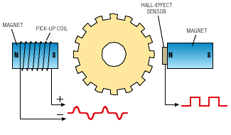
Hall effect senders are named as such for the type of signal they produce, a hall effect signal. This sender requires power and ground to operate. The benefeit of this sender is it can be accurate at very low speeds as it has a power source. It is generally identified by having 3 connections: Power, ground (sometimes through the body and the signal output). See images below for more.
AC sinewave speed sender
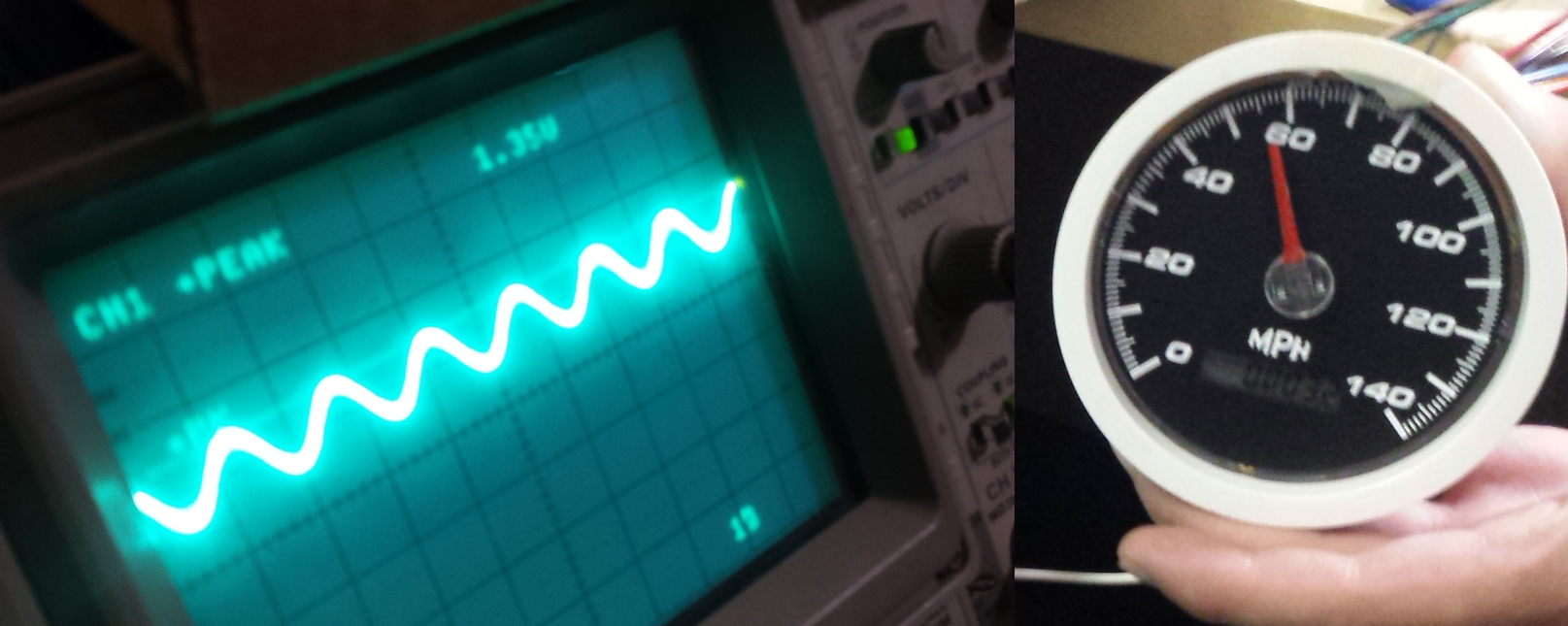
This type of sender, while more widely used in the 90s and early 2000's is simple and reliable. It generates its own power and sends an AC sinewave signal to the speedometer by teeth spinning past a coil with 2 wires. The sender requires one wire to be grounded and the other is the signal. The wires can be reversed and the same result will work just fine due to the fact that the sender waveform is a simple sinewave. The downside is that due to the sender generating its own power by the speed of the relustor wheel (teeth) it can often lead to a weak signal at low speeds. this is often seen when a speedometer will not operate until a certain speed, say 25-30 MPH. NVU electronic programmable speedometers have built-in sensitivity settings that can be changed to suit your signal strength. ONLY NVU speedometers have this capability removing the need for converters, boxes or additional equipment. One other disadvantage to this type of sender is the signal cannot be split to send pluses to multiple devices such as speedometer and cruise control.


PCM, ECU, Computer speed signal
Sounds complicated but this actually makes things easier. The speed signal is already being picked up from the source ans being sent to the PCM (Powertrain Control Module). The PCM then uses it as it needs and outputs a signal. The most commonly used for builds are PCMs for GM engines. Regardless if its an LS, LT, diesel 4, 6, or 8 cylinder GM PCMs always have 2 outputs (unless flashed by an aftermarket company):
1. The speed signal is a 4,000 PPM output. You will still have to do your drive a mile as the vehicles may have had different gears/tire sizes, but 4000 will get you close.
2. Not related to speed; GM PCMs regardless of engine size or type output a 4 cylinder open collector tachometer signal. This means you need to use a 10-K ohm pull-up resistor and set your tachometer to 4 cylinder.
Where are these speed senders and what do they look like?
As stated perviously, there are generally 2 types of speed signals, AC sinewave and Hall Effect. While there are only 2 types, they can be in different shapes and locations. See the images below to help identify the parts.
Screw-on speed senders: These are used in older transmissions which have a cable drive for spinning a mechanical speedometer. These units replace the cable entirely and are relatively inexpensive. A gear in the transmission engages the drive tang on the sender (generally .104"x.104") and spins the sender to create a signal. Why not just use a mechanical cable style? Calibration is the answer. To calibrate a cable-style speedometer the gear drive in the transmission must be changed. While not difficult, it does take time and trial and error. GM and Ford style are most common, VW are available from time to time. These can either be hall effect (3-wire) or AC sinewave (2-wire). NVU manufactures these units for use in aftermarket vehicles that may need this type of drive.
Integrated: This bolts onto the transmission or pickup area over a toothed wheel often referred to as a reluctor ring or wheel. This type is installed at the factory and if it requires replacement it will need the factory part. These can either be hall effect or AC sinewave.
PCMs, ECUs, Computers: Just to touch on the previous information the PCM (powertrain Control Module) reads input from a speed sender, usually existing in the vehicle system. Consult your PCM documentation for connecting to the correect VSS (Vehicle Speed Sender) wire or pin.

How to test an electronic speedometer
While we do have an extensive online troubleshooting guide for NVU speedometers, you can use the guide for any gauge, theory is the same whether its an OE or aftermarket gauge:
