

GM LS AND DURAMAX INSTALLS
NVU Tech Team on 3rd Nov 2016

We have calls daily on this so we thought it would be a great time to clear the air on how to connect aftermarket instruments to GM vehicles that have a PCM. Its easier than you think, just break down the installation in steps, no more difficult than any other gauge install.
Any aftermarket gauge set is a standalone system, that means that the gauges operate alone, and are not integrated into the vehicle system as in most modern vehicles. Similar in the way most of the LS PCM/Harness installations are done, the system is standalone and does not require the body or chassis controller(s) to be intact to operate properly. If you remember this, it will make things much easier.
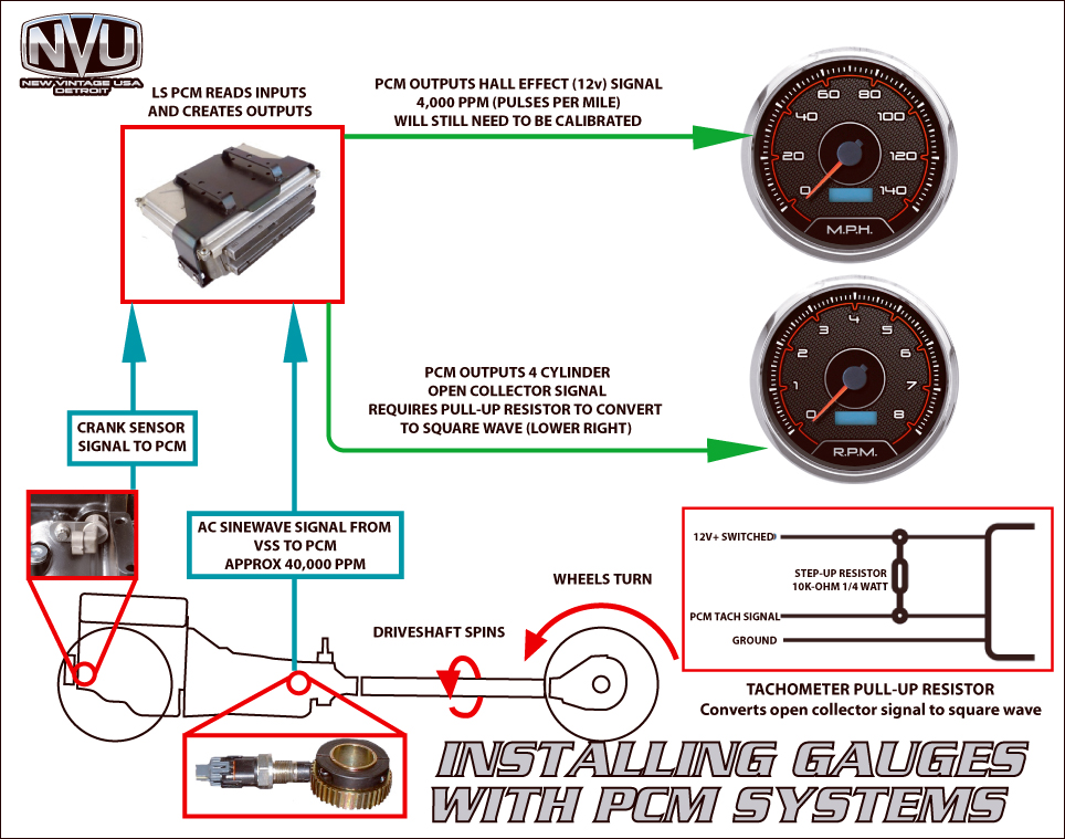
SPEEDOMETER:
VSS HI SIGNAL FROM PCM(varies depending on vehicle) SET PULSES TO 4,000
4k not perfect? You can also manually set your pulses in your speedometer to 4,000 to start off, you will most likely need to calibrate using a measured mile to get exact speed. The 4,000 PPM count from GM is a starting point, while the PCM is out-putting this signal, GM did not know your, rear end or tire size when the PCM was built so exact pulse counts will differ slightly.
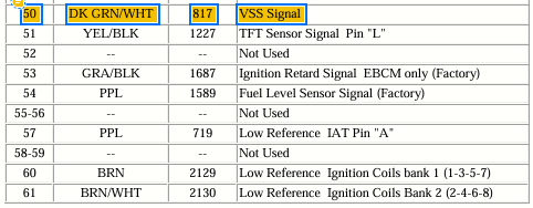
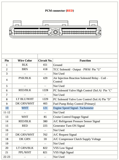
TACHOMETER:
PCM OUTPUT (varies depending on vehicle) SET CYLINDER TO 4
TACHOMETER NOTES:
In the event that your tachometer does not read any speed when connected properly and it HAS been "tuned", have your tuner make sure that the tach output is turned ON. We have seen this hundreds of times and is almost always the case with an unresponsive tachometer on a GM PCM.
NOTE: If you have a 5-DIP switch tach, no pull up required, just set DIP-switch #5 to "ON" and Gauge Cylinder selection set to 4 cylinder.
If you gauge has 4 dipswitches under its black round cover, check out the diagram below on how to wire in the 10k resistor necessary to boost the PCM tach signal.
The pull up resistor does not affect the cylinder count. If your PCM has been tuned (flashed) check with the company that updated the software to be sure of what the tachometer signal is and how many cylinders and if it has been changed from stock.
Our LS sender install video covers all of the odd-and ends of both the temp and pressure senders in-depth, check it out:
Water Temperature:
is done in the same manner as oil pressure, with a new, separate sender. The gauge sender will run just the gauge, the stock water temperature sender will remain in place and feed the PCM data to run the engine. Our LS kit also has the metric bushings for the water temperature.
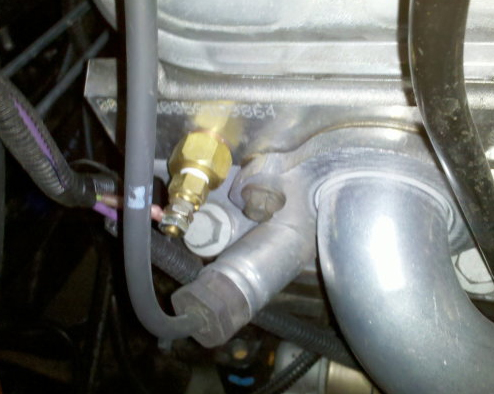
Oil Pressure:
For the best results we recommend using liquid type sealant on the threads, avoid Teflon that may cause grounding and longevity issues.
The LS has 2 possible locations for the pressure sender, both will require our LS kit part number 99009-04 or similar to adapt to the metric threads. this will not fit LT engines, for some reason GM changed the thread pitch.
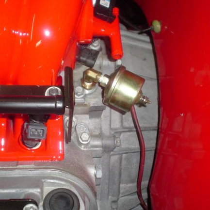
The first position is behind the intake manifold on the driver side. This is M16x1.5 and requires a gasket/seal (included in our LS kit). The image below shows an angle used, if possible, straight is easier and cleaner as long as you have clearance.
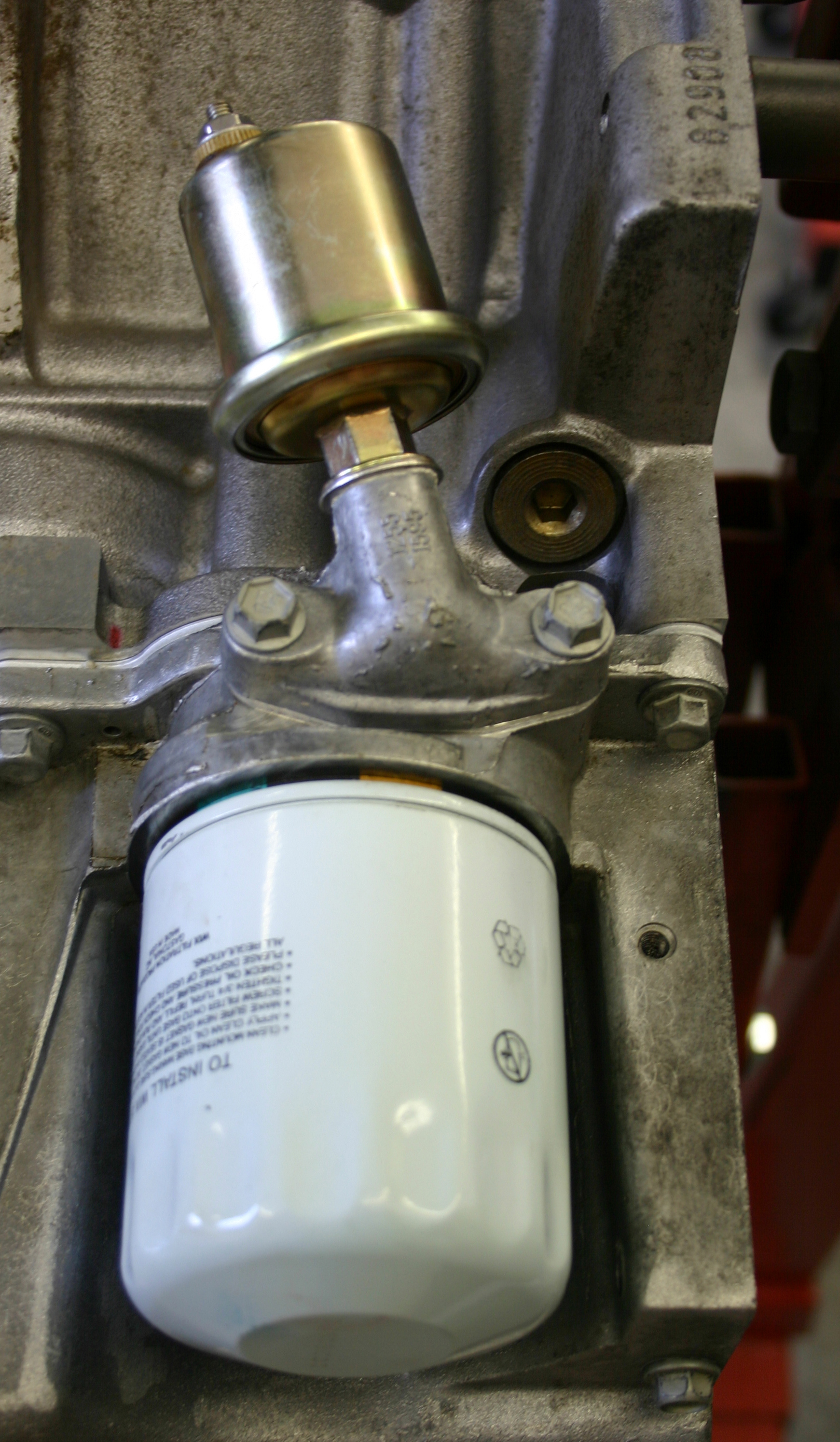
The second option is there is a port down by the oil filter. If this option works for you better and you have a truck block, you'll notice that the port may not be there. No problem, just remove the block-off plate and you can use an adapter that bolts on there. We have it shown both ways in our video above.
Fuel Level:
is done by running the fuel sender wire to the fuel gauge and is not connected to the PCM in any way on a transplant (new engine in old vehicle). Make sure the fuel gauge matches your instruction booklet.
Volts:
Are just volts and can be read from the 12V power coming in to the gauge, no reason to make this one overly complicated!
RELATED ARTICLES:
HOLLEY TERMINATOR/ TERMINATOR X-MAX INSTALLATION
FUEL SENDERS MORE THAN YOU WANTED TO KNOW!
USING SPEED SENDERS ON VARIOUS TRANSMISSIONS
EMI INTERFERENCE & HOW TO REMEDY