

INDICATORS, AUX INPUTS AND ICONS
NVU TECH DEPT. on 19th Mar 2025
We've built some pretty neat features into the Phoenix platform, let's take a look on how to use them. These are all optional features, if you don't need them, no worries just don't use them.
INDICATORS
Our indicators are built into each speedometer and tachometer with OLED screen. The number one call we get is "Hey, you forgot my blinkers!" We use a process called deadfronting which makes them invisible when off.
- All of the indicators are LED lights
- The indicator lights are triggered by 12V+
Thats it. Its just that easy.
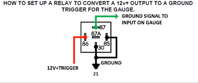
In the event that you want to trigger the lamp with a ground you will need to use a relay. these are available anywhere from your local auto parts store to Amazon.
The diagram below shows how to wire a relay for ground trigger:
Here is a simple video as well:
Each kit has a wiring diagram specific to how the indicators are wired, please check your instruction manual for the colors required. We even put an image of the gauge layout on the top to help you identify the proper diagram.
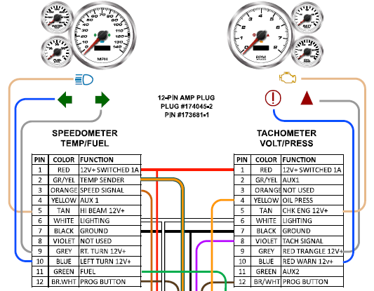
Speedometers and tachometers (8K gas) have the following schematic. Note the diagram shows the following:
- Which gauge it is on
- Indicator icon in color
- Indicator wire color
- A chart with text indicating the function
Remember these are all 12V+ triggered (12V+ power will make them turn on)
3-1s, Speedo/tach combination gauges and diesel tachometers are different, please refer to your wiring diagram for the proper colors and connections. The operation is the same across the product line.
AUXILLARY GAUGES ON OLED SCREENS
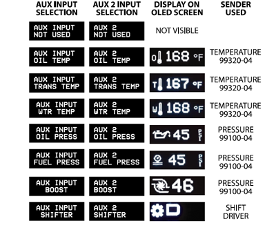
Another great feature that we include in our Phoenix gauges is built-in auxiliary gauges that can be displayed on the OLED screens. these are included and best of all you don't need any additional boxes, modules or drivers. The only thing you will need is the proper sender (temperature or pressure) to use properly. you must use NVU senders, or the readings will not be correct.
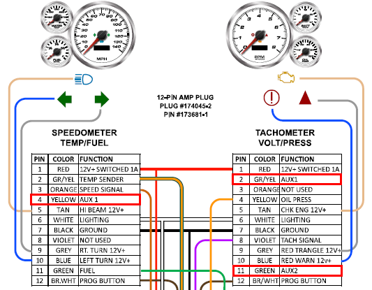
The auxiliary gauges on the screen can are activated using the AUX INPUT wires. On a 6-gauge kit there are:
1 AUX INPUT on the speedometer
2 AUX INPUTS on the tachometer.
To view them once set-up just scroll to that screen and it will remain active until you scroll to another function.
Below are the inputs available and the appropriate sender to be used for that function.
We also have a video covering the auxiliary icons and gauges right here:
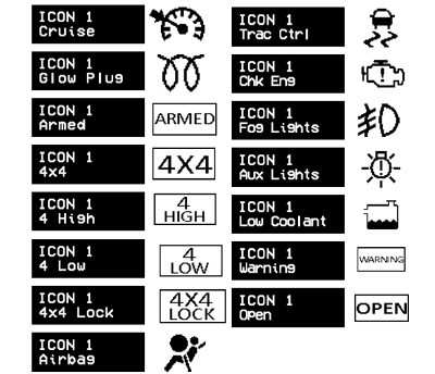
ICONS ON THE OLED SCREEN
Another great feature that is built in is our additional icons that can be displayed on either the speedometer or tachometer screen.
These are all triggered by a ground not power. This means that the icon will be displayed on the screen for 30 seconds when a ground is applied to the trigger. This means a switch of some sort that when connected is a ground. We use this most often on GM PCMs to show the check engine lamp.
We currently offer 15 additional icons that can be displayed:
The indicator icons on the screen can are activated using the AUX INPUT wires. On a 6-gauge kit there are:
1 AUX INPUT on the speedometer
2 AUX INPUTS on the tachometer.

Here is a good video covering connections and operation of the OLED icons:
This information should get you started, if you have any specific questions please don't hesitate to reach out and CONTACT US.