
Gauge meters, movements, motors and functions
NVU Tech Team on 4th Aug 2016

Our third installment of the NVU tech blog will cover types of gauges: mechanical, electronic, etc. People are always asking us which is better? The question comes down to which is better for your application.
Accuracy Vs resolution.
There is not any accuracy difference between any of the movement mentioned in this article. All accuracy comes from the components and programming along with the correct senders. Stepper motor gauges (like mechanical gauges) may have higher RESOLUTION due to the fact that the sweeps are generally full (260-270 degree). This higher degree of sweep has more degrees of movement when compared with a 90 degree gauge.
Mechanical
There are 2 basic types of mechanical gauges. One style uses pressure the other uses a spinning cable.
Bourdon tube gauges for pressure and temperature.There is generally a threaded port on the back of the gauge that has a pressure or capillary tube connected. Pressure is read directly from the engine or in the case of a temperature gauge, a capillary tube is used. In the capillary tube, the temperature is read at the end, and just like a thermometer, the liquid as it heats, expands, creating pressure.
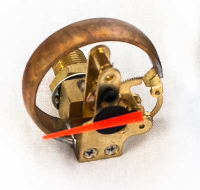
Bourdon tube style movement with gear train
When the fluid or gas expands inside the tube, the bourdon inside the gauge also expands or contracts driving the gear train, which then turns the pointer.
Liquid filled mechanical gauges are designed for racing. Contrary to popular belief, the liquid inside is not for fogging. The liquid is for anti-vibration to smooth out the pointer and dampen it.
Pros:
Generally inexpensive
Reaction time is quick
Cons:
Must run tubing through firewall
Over time gear train can fail due to grease, dust
Over or under pressures can drive pointer off gear train causing mis-calibration
What makes a mechanical gauge accurate consistently is the material has to be EXACTLY the same every time. "Value" mechanical gauges may suffer from this. Another thing that may play a role is each mechanical gauge must be "tweaked" by the assembler to achieve the proper calibration. Often the tube or gear lever is bent slightly to achieve the proper readings. This user-error/training can also play a part in how accurate a mechanical gauge may be. Industrial applications of mechanical gauges are usually certified, which means that each part is made to exacting specifications, including the bourdon tube material, which does make them a more expensive product.
The next type of mechanical gauge is a rotational driven unit for a speedometer or tachometer. A cable spins in the back of the unit and drives a magnet. This magnet then has a cup over the top and a spring holding it back to zero. The spinning magnet working against the spring moves the pointer.
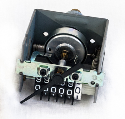
Mechanical speedometer driven by a spun shaft with odometer
Many of the mechanical drive units have a gear train that will drive an odometer or even an hourmeter.
Pros:
Easy to install
Cons:
Calibration is done by changing out drive gear in the transmission
Re-settable trip requires a hole in the lens with a knob or back (not waterproof)
Electronic instruments
Electronic gauges are built in 2 basic platforms. Air core and stepper motor. While both of these technologies have been around for some time, there are some really close similarities and some very different components at the same time.
Air Core Meter Instruments
Air core instruments are named for the meters that drive the pointer and fall into short and full sweep categories. Short sweep air core gauges use a single winding meter. This is basically half of an electric motor with the windings on the outside and a shaft on the inside that spins.
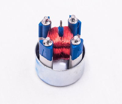
Single winding air core meter with 90 degree clockwise sweep
Short sweep meters are very simple devices, they only require power, ground and a signal, usually resistance to ground or voltage. The sender (resistance to ground) varies the current through the meter and thus changes the magnetic field, rotating the shaft and pointer. Most air core meters have a metal cup (shown above dropped for better viewing) that will help shield any magnetic forces that may interfere with the gauge reading accurately.
While air core gauges are generally perimeter lit, they can also be backlit, the air core refers to the meter inside the unit itself. What makes an air core meters appealing to instrument manufactures is they are virtually bullet-proof. With only one floating, moving part there is very little to fail. What makes them accurate consistently is that the winding and shaft material must be manufactured exactly the same way every time or the unit will not be the same each time. Calibration is also much easier than a mechanical, bourdon tube style as the calibration unit does most of the work. A gauge is powered up and a signal sent, the pointer is then placed on in the correct position. Little room for user error.
RETURN TO ZERO (RTZ): NVU air core gauges in full or short sweep do not have a true RTZ function, they rest around zero. Some manufacturers use a larger sweep or a spring to being the gauge back to a rest position. We leave the pointers to rest where they may at off position to eliminate any pointer stops on the dials if at all necessary for a clean look for the graphics.
Pros:
Very fast to react
Durable
Medium price
Simple to troubleshoot
Cons:
Limited to 90 degree sweep
Must have exact matching sender to operate properly.
Usually not dampened. Dampened units have a silicone fluid which can leak out if stored face down.
Each winding can only perform one purpose or direction
Multiple wingdings needed to create a full set of functions
Full Sweep Air core gauges
Similar in construction to short sweep, but with a dual (full) winding. This will allow for a full 360 degree rotation if desired. With a dual winding, there a 4 connections, 2 power and 2 ground. These two winding acting in concert will move the pointer in any direction within the 360 degree circle.
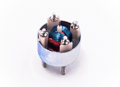
Dual winding full sweep air core meter
The current is controlled by a circuit board with various components, the most important is the air core chip. A full sweep gauge can be pulsed inputs (for a speedometer or tachometer) or inputs to ground, or even voltage.
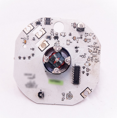
Full sweep tachometer board with circuitry and air core driver chip
The image above shows a typical full sweep gauge, in this case a tachometer. Regardless of the input, the basics are the same. A signal is sent into the gauge and then the circuitry reads it. The air core chip will then vary the voltage and move the pointer to the desired position.
Pros:
Fast reaction
Cons:
Torque not as high as,stepper motor. Pointers need to be balanced and not overly long.
Circuit board/drivers drives complexity and cost.
Stepper Motor Movements
Stepper motor gauges are very versatile and appear in a wide range of applications. The large number of chips available to run them makes for a good platform that can be expanded upon. Stepper motors do exactly that; step. They move in a series of steps. Older or commercial units may have a "ticky" movement as the pointer moves. This is generally from how the code is setup or the amount of memory available on the driver chip. Smooth sweeping is achieved with higher memory chips and programming microstepping. This is fractional movement of the pointer through each step. While both are equally accurate, microstepping provides a more fluid movement that is purely aesthetic.
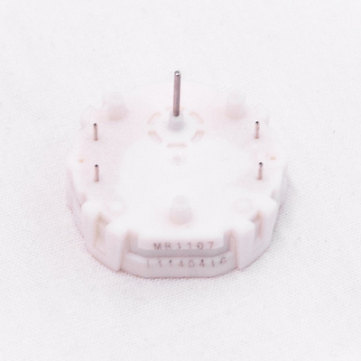
Front mount stepper motor
Inputs are similar to a full sweep aircore gauge; resistance to ground, voltage or pulsed. The signal comes in to the circuit board and the circuitry filters it to the driver chip. The driver chip, with the programming moves the motor shaft which in turn moves the pointer. Once the chip indicates where the pointer should "step" to, the pointer will remain there as long as the gauge is powered. This high-torque holding is perfect for longer or un-balanced pointers or high side force applications.
Stepper motors come in a wide range of shaft sizes and mounting. This can enable the same base code to be used for various inputs and dial readings. Front mount stepper motors are actually attached to the back of the circuit board. This makes for a slim package and allows for pointer LED lights to be mounted directly on the board. The challenge with lighting the dial on this setup is the lights that actually illuminate the dial are also on the board and are very close to the dial, creating hot spots that then need to be light compensated with the artwork. Other light diffusion techniques may also be used like filtering refactors or materials.
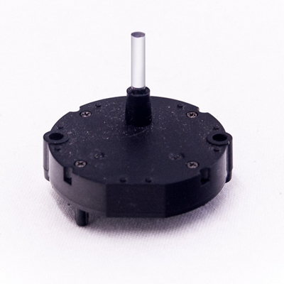
Rear mount stepper motor
The mounting may influence the lighting style or position of other functions such as lights, plugs, etc. In most cases, a front mount (actually goes on the back of the board) will be used in a slim design. A rear mount (on the front of the board) will be in a deeper package, will offer better backlighting but it is more difficult to light the pointer.
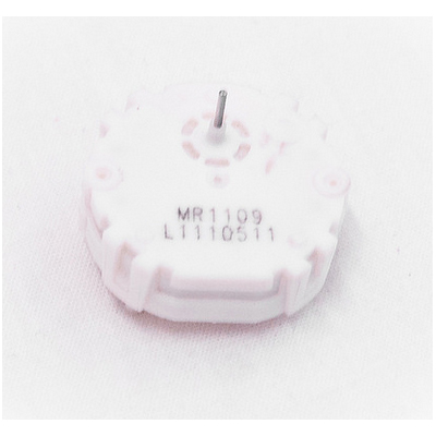
Lighted shaft stepper motor
Another option for instrument builders is a lighted shaft stepper motor. This is a rear mounted (on the front of the board) with an LED under the shaft that will light through the shaft, up through the pointer. This sets the lighting back farther for a smoother effect when using backlighting while solving the pointer lighting issue.
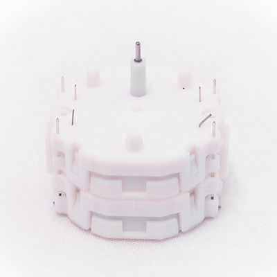
Dual shaft stepper motor
Dual shaft stepper motors are actually 2 units on top of each other with 2 shafts. The individual motors can be operated independently of each other. This will allow 2 separate functions in one gauge using a single center pivot. The drawback is pointers that are unique to this design must be used along with a unique deeper case.
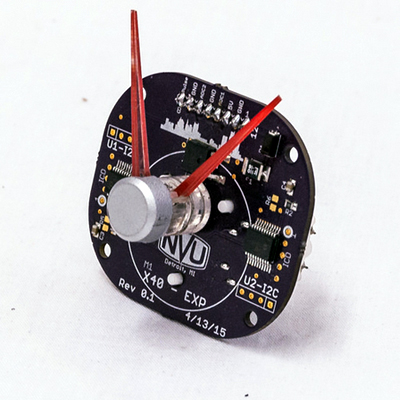
Concept dual shaft tachometer board with telltale
Dual shaft stepper motors in use for clock have a single motor with a 60:1 gear ratio for the 2nd pointer. The motor is then driven by a standard clock chip that is readily available.
One of the advantages of a stepper motor driven instrument is programming flexibility. Below is a design from here at NVU where the user can select from up to 18 different inputs for fuel level. This can also be programmed with dampening , pointer speed and direction.
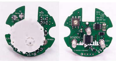
NVU programmable input fuel gauge with dampening
Stepper motor pros:
Wide range of functions from one base unit
Can be dampened with programming
Can be any sweep or sweep direction
High torque for longer pointers
Stepper motor itself is generally inexpensive and common drivers across manufacturers
Once programmed, calibration and self testing are easy
Multiple inputs can be used on some models.
Stepper motor cons:
Circuitry required to drive unit
Manufacturer/designer must have knowledge of coding
More complexity drives cost
Conclusion
Each instrument construction style has its own advantages and disadvantages. Each has their own limitations and no one is better that the other in many respects. It all comes down to what has the functions and features the end user desires and what the application may be.