

SMALL BLOCK CHEVY INSTALLATIONS
NVU TECH DEPT. on 14th Mar 2025
Still the most popular engine in the hot-rodding world! Integrating NVU gauges with these is about as easy as it gets.
SPEEDOMETER (CABLE STYLE):
GM CABLE REPLACEMENT STYLE 99001-04
These setups are for vehicles that have a mechanical cable driving your speedometer. These transmissions have an integrated gear that is part of the housing. The tooth count of the gear is not important as the speedometer will be calibrated to your specific vehicle.
APPLICATIONS:
Works on all cable-style GM/Chrysler transmissions, these are generally 7/8-18 thread with a .104" drive tang.
TH350
TH400
TH200 -Some have an integrated speed sender, see section below
TH400 -Some have an integrated speed sender, see section below
Installation is super easy, simply remove your original cable and you will have this:
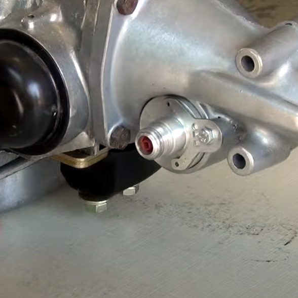
Then align the square drive with the gear and screw on snug. The sender has a rubber seal, so a good snug fit is all you need.
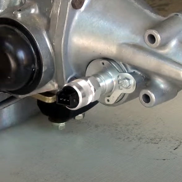
Wire up as the instructions show:
RED: 12V Switched power (same as your gauges)
BLACK: Ground
WHITE: Signal to speedometer, orange wire on the 12-pin harness.
Calibration is easy, we have a simple video here:
SPEEDOMETER (2-WIRE OE STYLE SENDER):
NVU speedometers are compatible with most OE speed senders. What's great about these is they are already there-nothing to buy!
This section will cover connecting directly to the speed sender. This is an option only when your PCM does not require a signal. LS swaps and aftermarket controllers will need the signal to operate properly, from there the PCM or controller will send out a signal to the speedometer. Check out our TECH BLOG and TECH VIDEOS for even more info on those types of setups.
This type of sender, while more widely used in the 90s and early 2000's is simple and reliable. It generates its own power and sends an AC sinewave signal to the speedometer by teeth spinning past a coil with 2 wires. The sender requires one wire to be grounded, and the other is the signal. The wires can be reversed, and the same result will work just fine due to the fact that the sender waveform is a simple sinewave.
The downside is that due to the sender generating its own power by the speed of the reluctor wheel (teeth) it can often lead to a weak signal at low speeds. this is often seen when a speedometer will not operate until a certain speed, say 25-30 MPH. NVU electronic programmable speedometers have built-in sensitivity settings that can be changed to suit your signal strength. ONLY NVU speedometers have this capability removing the need for converters, boxes or additional equipment. One other disadvantage to this type of sender is the signal cannot be split to send pluses to multiple devices such as speedometer and cruise control.
This is what it looks like inside:
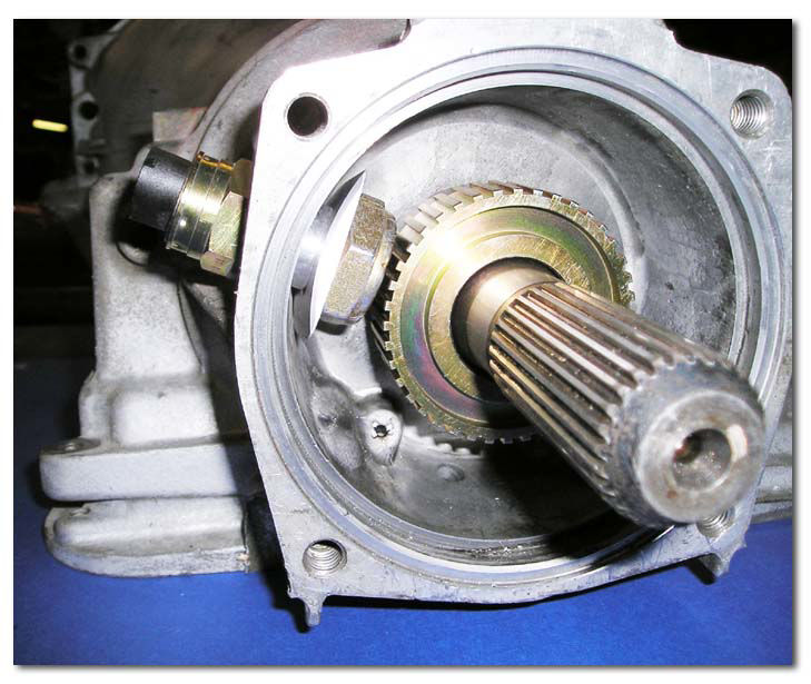
Typical OE style speed sender:

WIRING:
One wire is ground (keep the ground short for a good signal)
The other wire is the signal, this goes to the orange wire on the speedometer.
You cannot split the signal on 2-wire senders, if needed, a splitter may be required for cruise control.
Calibration is easy, we have a simple video here:
GPS SPEED SENDER 99010-04
Don't feel like messing around with all of that? No problem, our GPS speed sender has been out most popular accessory for over a decade! 1000s of them are on the road right now!

TACHOMETER:
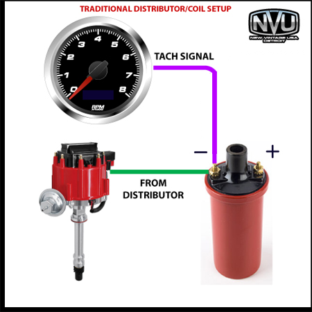
TRADITIONAL COIL INSTALLATION:
This setup uses a traditional distributor/coil. The tach reads from the negative side of the coil. The green is shown for clarity and may be a different color in your application.
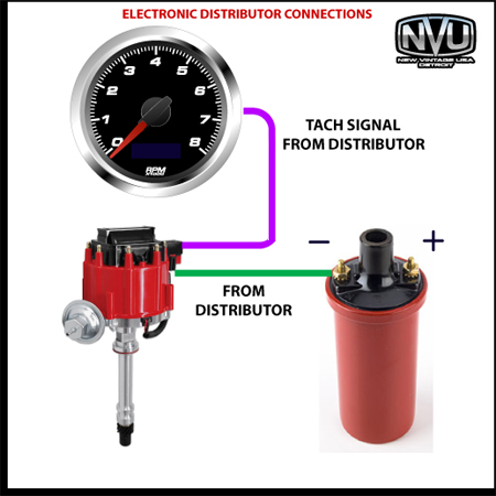
ELETCRONIC IGNITION DISTRIBUTOR/HEI PERTRONIX (SEE NOTE)
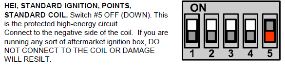
Most distributors built after 1976 use an electronic module instead of points and have a TACH OUTPUT right on the distributor. This output generally has a 12V square wave signal, It may be "high" or "low" voltage. Either way it is designed for a tachometer to see.
PERTRONIX SYETEMS: We recommend using a 1K resistor inline to prevent damage to the tachometer circuit.
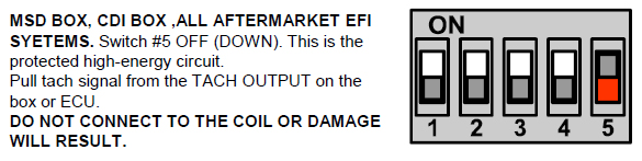
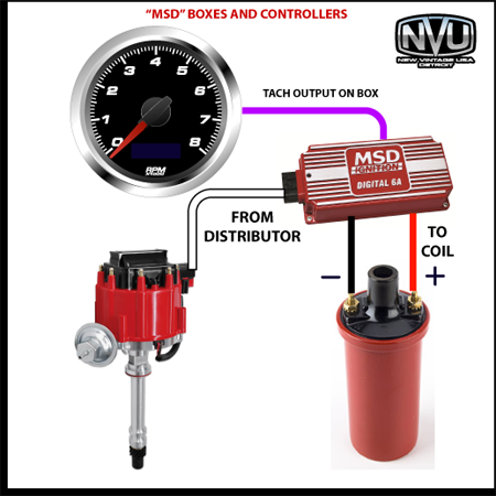
"MSD" BOXES AND OTHER IGNITION CONTROLLERS
This is probably the most popular ignition setup for aftermarket ignitions. The "MSD" box is a Multiple Spark Discharge system (MSD) which can generate up to 60,000 sparks (pulses) per spark plug firing. EVERY system like this has a tach output right on the box. It is either a 12V or 5V square wave signal designed to be clean for a tach to read. Notice the box has power and ground going to the coil. This creates a high voltage feedback that will damage the tachometer input. This is exactly why a separate output is used.
We looked up some different aftermarket ignition tach schematics and they are all over the place. Take a look HERE
WATER TEMPERATURE AND OIL PRESSURE SENDERS
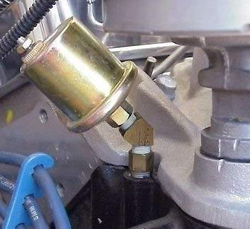
The oil pressure port is located on the driver side below the distributor. Many times, you may require a 45- or 90-degree elbow to get the proper clearance. We have used brass, galvanized and black pipe for decades without any issues. We just recommend not making the pipe too long as vibration may cause cracking of the pipe.
Below is a typical installation using a 45-degree elbow. Use liquid sealant and avoid Teflon tape.
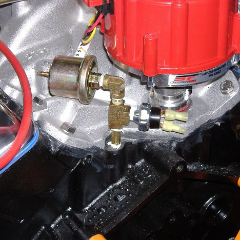
The next image shows splitting the pressure sender and adding a warning switch. this is about as "long" of an adaptation we would like to see.
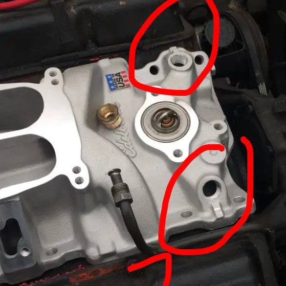
There are several potential locations for your temperature sender. It’s up to you to decide what's best for your installation, it may come down to space or appearance on your build.
The first 2 are in the intake manifold. Depending on the manufacturer of your intake, there may be several locations to choose from. Thread size may differ from manufacturers, but they are generally NPT sizes and our standard bushing kit that came in your gauge kit can be used. Like small block fords, you can also use a thermostat housing/water neck with a temperature sender provision. again, thread size will vary based on the manufacturer.
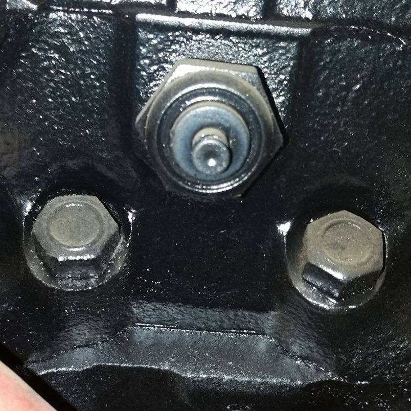
The second is on one of the cylinder head ports. This is usually 1/2" but may vary by year and if its an aftermarket head. These are generally NPT size and our adapter kit that came with your gauge kit should work well for this.
VOLTS AND FUEL
VOLTS is internally monitored, and no additional wiring is required.
FUEL LEVEL is read from your fuel sender in the fuel tank. Our Phoenix Platform gauges have fully programmable, dampened fuel gauges that can work on just about any tank/sender. We have a comprehensive article on how to use, set-up and test fuel senders and gauges RIGHT HERE>>>>